
Free course recommendation: Master JavaScript animation with GSAP through 34 free video lessons, step-by-step projects, and hands-on demos. Enroll now →
In this tutorial, we will guide you through the process of creating an interactive 3D dice roller using the JavaScript libraries Three.js for creating 3D graphics, and cannon-es for adding interaction. We will start by building the dice using modified BoxGeometry and without using textures, shaders, or external 3D models. Then, we will use cannon-es to incorporate physics, simulate the dice roll and detect the landing side.
Coding the dice
Of course, it’s possible to find a ready-made dice model on the web or create one in Blender, but let’s make it programmatically using Three.js. After all, we’re learning here 🙂
The dice geometry will be based on THREE.BoxGeometry, but modified to round the box corners and add notches on the sides.
Rounding the edges of the box
Rounding the corners of a box is a quite common task, so there are multiple solutions available for it. One such solution is included in the Three.js package: RoundedBoxGeometry extends the BoxGeometry class and can be found under the examples/jsm/geometries/ folder.
The RoundedBoxGeometry class works for any box size and provides the configurable geometry with UV and normals included. If you do not need any additional geometry modifications over it, RoundedBoxGeometry is likely the perfect out-of-the-box (ba dum tss!) solution.
The RoundedBoxGeometry allows to set a number of segments for the rounded area, but flat surfaces are always built with one pair of triangles.

RoundedBoxGeometryThis limitation makes us unable to add the notches to the sides of the box so we make a custom solution for rounding the edges.
As a base, we take a cube as BoxGeometry with a decent number of segments.
const params = {
    segments: 50,
    edgeRadius: .07
};

let boxGeometry = new THREE.BoxGeometry(1, 1, 1, params.segments, params.segments, params.segments);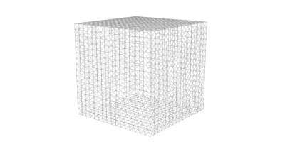
Practically, geometry modification means looping through the box vertices to access the XYZ coordinates in the boxGeometry.attributes.position array. Once the XYZ coordinates are changed, they can be reapplied to the position attribute.
function createDiceGeometry() {
    let boxGeometry = new THREE.BoxGeometry(1, 1, 1, params.segments, params.segments, params.segments);
    const positionAttribute = boxGeometry.attributes.position;

    for (let i = 0; i < positionAttribute.count; i++) {

        let position = new THREE.Vector3().fromBufferAttribute(positionAttribute, i);

        // modify position.x, position.y and position.z

        positionAttribute.setXYZ(i, position.x, position.y, position.z);
    }

    return boxGeometry;
}
Please note that we don’t code the universal solution like RoundedBoxGeometry. Since we make a cubic shape, we cover only the case when all the sides of the box are equal to 1. We also don’t bother calculating UV coordinates as there is no texture to be applied to the dice.
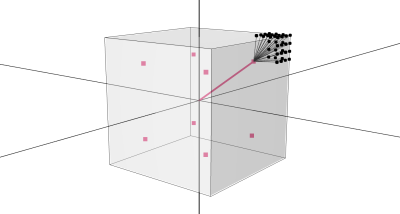
Let’s start with selecting the coordinates (vertex positions) that are close to the box edges. As we have a box side equal to 1, we know that the X, Y, and Z coordinates vary from -0.5 to 0.5.
If all 3 vertex coordinates are close to -0.5 or 0.5, the geometry vertex is close to the box vertex (let’s try not to confuse the geometry vertices we modify with the eight box vertices we’re rounding).
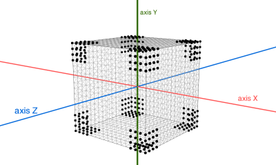
If only 2 of 3 coordinates are close to -0.5 or 0.5, the geometric vertex is close to the edge of the box. Other vertices keep the original position. For example, if X and Y coordinates are close to -0.5 or 0.5, the vertex is close to the edge parallel to axis Z.
This way, we select all the geometry vertices that should be modified:
function createDiceGeometry() {
// ...
const subCubeHalfSize = .5 - params.edgeRadius;
for (let i = 0; i < positionAttribute.count; i++) {
// ...
if (Math.abs(position.x) > subCubeHalfSize && Math.abs(position.y) > subCubeHalfSize && Math.abs(position.z) > subCubeHalfSize) {
// position is close to box vertex
} else if (Math.abs(position.x) > subCubeHalfSize && Math.abs(position.y) > subCubeHalfSize) {
// position is close to box edge that's parallel to Z axis
} else if (Math.abs(position.x) > subCubeHalfSize && Math.abs(position.z) > subCubeHalfSize) {
// position is close to box edge that's parallel to Y axis
} else if (Math.abs(position.y) > subCubeHalfSize && Math.abs(position.z) > subCubeHalfSize) {
// position is close to box edge that's parallel to X axis
}
// ...
}
// ...
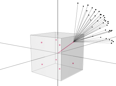
}First, let’s round the geometry vertices that are close to the box vertices. We want to replace their original position with XYZ coordinate lying on the sphere placed in the corner of the box.
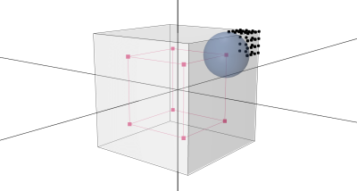
To transform position vector this way, we break it to two components:
subCube– vector that points to the box with that’s smaller than original one by rounding radiusaddition– the rest ofpositionvector
for (let i = 0; i < positionAttribute.count; i++) {

    const subCubeHalfSize = .5 - params.edgeRadius;

    // ...

    const subCube = new THREE.Vector3(
        Math.sign(position.x),
        Math.sign(position.y),
        Math.sign(position.z)
    ).multiplyScalar(subCubeHalfSize);

    const addition = new THREE.Vector3().subVectors(position, subCubeEdges);

    // ...
}
The original vertex position is a sum of subCube and addition vectors. We keep subCube without change because it points to the sphere center. The addition vector we normalize so it points to the sphere with a radius = 1
… and multiply it by the rounding radius value to move coordinate on the desired sphere.

for (let i = 0; i < positionAttribute.count; i++) {

    // ...

    const subCube = new THREE.Vector3(Math.sign(position.x), Math.sign(position.y), Math.sign(position.z)).multiplyScalar(subCubeHalfSize);
    const addition = new THREE.Vector3().subVectors(position, subCube);

    if (Math.abs(position.x) > subCubeHalfSize && Math.abs(position.y) > subCubeHalfSize && Math.abs(position.z) > subCubeHalfSize) {
        // position is close to box vertex
        addition.normalize().multiplyScalar(params.edgeRadius);
        position = subCube.add(addition);
    }

    // ...
}
With code above we can round all the cube vertices.

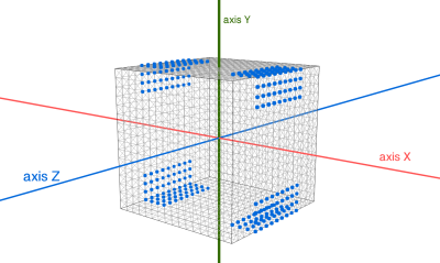
The same approach works for the box edges. For example, take the geometry vertices that are close to the box edges parallel to the Z-axis. Their position.z is already correct, so only the X and Y coordinates need to be modified. In other words,
position.zis not modifiedaddition.zshould be set to zero before normalizingadditionvector

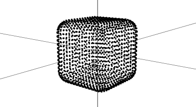
Repeating it for other axes, we get a rounded cube geometry.
let position = new THREE.Vector3().fromBufferAttribute(positionAttribute, i);

const subCube = new THREE.Vector3(Math.sign(position.x), Math.sign(position.y), Math.sign(position.z)).multiplyScalar(subCubeHalfSize);
const addition = new THREE.Vector3().subVectors(position, subCube);

if (Math.abs(position.x) > subCubeHalfSize && Math.abs(position.y) > subCubeHalfSize && Math.abs(position.z) > subCubeHalfSize) {
    addition.normalize().multiplyScalar(params.edgeRadius);
    position = subCube.add(addition);
} else if (Math.abs(position.x) > subCubeHalfSize && Math.abs(position.y) > subCubeHalfSize) {
    addition.z = 0;
    addition.normalize().multiplyScalar(params.edgeRadius);
    position.x = subCube.x + addition.x;
    position.y = subCube.y + addition.y;
} else if (Math.abs(position.x) > subCubeHalfSize && Math.abs(position.z) > subCubeHalfSize) {
    addition.y = 0;
    addition.normalize().multiplyScalar(params.edgeRadius);
    position.x = subCube.x + addition.x;
    position.z = subCube.z + addition.z;
} else if (Math.abs(position.y) > subCubeHalfSize && Math.abs(position.z) > subCubeHalfSize) {
    addition.x = 0;
    addition.normalize().multiplyScalar(params.edgeRadius);
    position.y = subCube.y + addition.y;
    position.z = subCube.z + addition.z;
}
Updating the normals
Often, simply calling the computeVertexNormals() after modifying the geometry vertices is sufficient to update their normals. The method computes normal for each vertex by averaging the normals of neighbour faces (of faces that share this vertex). It’s a very easy way to smooth geometry, unless geometry has duplicated vertices.
It’s common to have 1+ geometry vertices placed on the same position, mainly to maintain the UV and normal attributes. For example, take THREE.CylinderGeometry. The side surface has a seam that’s visible on the left picture. There are two sets of vertices sitting on this vertical seam line. The duplicated vertices have the same position and same normal but different a UV attribute. The first set of vertices is connected to the faces on the left to the seam line (UV.x = 1), and the second set of vertices is connected to the faces on the right side from the seam (UV.x = 0). Duplicated vertices are necessary to properly wrap the texture around the side and, in case of cylinder, to support thetaLength parameter.
Of course, THREE.CylinderGeometry is coming with properly calculated normals like you see on the central picture.

CylinderGeometry with texture (left), original normals (center), automatically recalculated normals (right)But if we call cylinder.geometry.computeVertexNormals() (even without any geometry modification) the normals would turn to what you see on the right picture. The average face normals are different for left and right set of duplicated vertices.
const material = new THREE.MeshNormalMaterial({});
const cylinder = new THREE.Mesh(new THREE.CylinderGeometry(1, 1, 2, 9), material);
// here normals are correct (central pic)

cylinder.geometry.computeVertexNormals();
// here normals have a seam (right pic)
THREE.BoxGeometry has duplicated vertices on the box as well. They’re placed on the box edges. That’s why we can easily map textures on the each side of the box… and that’s why we have similar problem with seams.
The picture below shows original box normals on the modified geometry
With extra vertices on the box edges, the computeVertexNormals() doesn’t produce the correct result.
To fix the seams we need to remove all duplicated vertices before calling computeVertexNormals(). It can be easily done with mergeVertices() method which meant to delete the vertices with very same set of attributes. Duplicated vertices have normal and uv attributes inherited from BoxGeometry that we delete. Once it’s done, duplicated vertices have only a position attribute and vertices with same position that can be automatically merged.
// mergeVertices() requires the import of BufferGeometryUtils file
import * as BufferGeometryUtils from 'three/addons/utils/BufferGeometryUtils.js';

// ...
// all the modifications of geometryBase.attributes.position

geometryBase.deleteAttribute('normal');
geometryBase.deleteAttribute('uv');
geometryBase = BufferGeometryUtils.mergeVertices(geometryBase);

geometryBase.computeVertexNormals();
With the code above we complete the rounded cube.

P.S. To fix the normals of rounded cube, it’s also possible to simply re-use the addition vector instead of merging the vertices and recomputing normals:
const normalAttribute = boxGeometry.attributes.normal;
// ...
normalAttribute.setXYZ(i, addition.x, addition.y, addition.z);
It’s an easy and elegant solution but we want to automatically update the normals again after the next geometry modification. So for today’s project we stick with a combination of mergeVertices() and computeVertexNormals().
Applying notches to the sides
The next step is to add one to six smooth hollows to the sides of the cube. To start, let’s add one to the center of top side. We can select the top side vertices simply by checking if the position.y value equals to 0.5. For selected vertices, we’d decrease position.y by height of the notch.
The challenge is about calculating the notch shape. Let’s think about 2D space first and form a centered symmetrical smooth impulse on the XY coordinates.
First step is a cosine function for a wave with a peak at x = 0.

Then make it a positive number by adding 1 to Y.

The period of cosine is 2 x π, meaning the central wave starts at x = –π and ends in x = π. It would be more handy to have it from -1 to 1, so we multiply x by π.

As we need only a single wave at the center, we limit x value to be from -1 to 1.

Great! The impulse can be parameterized with PULSE_WIDTH and PULSE_DEPTH variables and that’s how we use it for the dice notch.
See the Pen Pulse shape step by step (Canvas and plain JavaScript) by Ksenia Kondrashova (@ksenia-k) on CodePen.
Turning the shape into 3D space is pretty easy. The 2D wave defines Y as a function of X. To make Y a function of both X and Z, we just multiply two waves – first one taken as a function of X and second as a function of Z.
const notchWave = (v) => {
    v = (1 / params.notchRadius) * v;
    v = Math.PI * Math.max(-1, Math.min(1, v));
    return params.notchDepth * (Math.cos(v) + 1.);
}
const notch = (pos) => notchWave(pos[0]) * notchWave(pos[1]);
So, for the top side we subtract the notch([position.x, position.z]) value from position.y, and similarly for other sides of the box. As our impulse is centered at the (0, 0) point, we can shift the notches around the side surface by adding the offset to the notch function arguments.
const offset = .23;

if (position.y === .5) {
    position.y -= notch([position.x, position.z]);
} else if (position.x === .5) {
    position.x -= notch([position.y + offset, position.z + offset]);
    position.x -= notch([position.y - offset, position.z - offset]);
} else if (position.z === .5) {
    position.z -= notch([position.x - offset, position.y + offset]);
    position.z -= notch([position.x, position.y]);
    position.z -= notch([position.x + offset, position.y - offset]);
} else if (position.z === -.5) {
    position.z += notch([position.x + offset, position.y + offset]);
    position.z += notch([position.x + offset, position.y - offset]);
    position.z += notch([position.x - offset, position.y + offset]);
    position.z += notch([position.x - offset, position.y - offset]);
} else if (position.x === -.5) {
    position.x += notch([position.y + offset, position.z + offset]);
    position.x += notch([position.y + offset, position.z - offset]);
    position.x += notch([position.y, position.z]);
    position.x += notch([position.y - offset, position.z + offset]);
    position.x += notch([position.y - offset, position.z - offset]);
} else if (position.y === -.5) {
    position.y += notch([position.x + offset, position.z + offset]);
    position.y += notch([position.x + offset, position.z]);
    position.y += notch([position.x + offset, position.z - offset]);
    position.y += notch([position.x - offset, position.z + offset]);
    position.y += notch([position.x - offset, position.z]);
    position.y += notch([position.x - offset, position.z - offset]);
}
We insert this code after the first geometryBase.attributes.position modification and get the dice mesh ready.

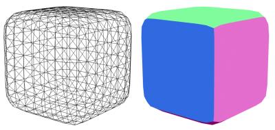
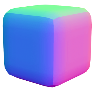
Applying colors
To color the dice, we just apply a grey MeshStandardMaterial to it.

To color the notches, we can make a simple trick and place six planes inside the cube so they come out from the notches.

We finish up the dice by coloring the inner panels in black and grouping them with the main mesh.
function createBoxGeometry() {
    let boxGeometry = new THREE.BoxGeometry(1, 1, 1, params.segments, params.segments, params.segments);

    // ...
    // modify boxGeometry.attributes.position and re-calculate normals

    return boxGeometry;
}

function createInnerGeometry() {

    // keep the plane size equal to flat surface of cube
    const baseGeometry = new THREE.PlaneGeometry(1 - 2 * params.edgeRadius, 1 - 2 * params.edgeRadius);

    // place planes a bit behind the box sides
    const offset = .48;

    // and merge them as we already have BufferGeometryUtils file loaded :)
    return BufferGeometryUtils.mergeBufferGeometries([
        baseGeometry.clone().translate(0, 0, offset),
        baseGeometry.clone().translate(0, 0, -offset),
        baseGeometry.clone().rotateX(.5 * Math.PI).translate(0, -offset, 0),
        baseGeometry.clone().rotateX(.5 * Math.PI).translate(0, offset, 0),
        baseGeometry.clone().rotateY(.5 * Math.PI).translate(-offset, 0, 0),
        baseGeometry.clone().rotateY(.5 * Math.PI).translate(offset, 0, 0),
    ], false);
}

function createDiceMesh() {
    const boxMaterialOuter = new THREE.MeshStandardMaterial({
        color: 0xeeeeee,
    })
    const boxMaterialInner = new THREE.MeshStandardMaterial({
        color: 0x000000,
        roughness: 0,
        metalness: 1,
        side: THREE.DoubleSide
    })

    const diceMesh = new THREE.Group();
    const innerMesh = new THREE.Mesh(createInnerGeometry(), boxMaterialInner);
    const outerMesh = new THREE.Mesh(createBoxGeometry(), boxMaterialOuter);
    diceMesh.add(innerMesh, outerMesh);

    return diceMesh;
}
See the Pen Configurable Dice (Three.js geometry) by Ksenia Kondrashova (@ksenia-k) on CodePen.
Next we’ll go into the animation. Please note that the second part of this tutorial doesn’t really depend on the first one and vice-versa.
Choosing the animation tool
Quoting any tutorial about this topic, I must say that Three.js is a tool to draw 3D scenes in the browser. It doesn’t include a physics engine or other built-in tools to help with animations. To avoid any confusion, the Three.js Animation system is an API that is mostly used to run the animations for imported models. It doesn’t help much to create new transitions (except KeyframeTrack but it’s quite basic).
To add motion and interaction to the scene, we need to calculate the values of the animated properties for each frame. The animated property can be a transform of a 3D object, color of material, or any other attribute of Three.js instance.
The calculation of the animated property can be as simple as incrementing it in the requestAnimationFrame() loop or as complex as importing some game engine to calculate the transforms.
The nature and complexity of a transition would determine the choice of the animation tool.
- For basic conditions, linear transitions and simple easing, interpolations, and other trivial calculations, keep it without extra libs.
- Use GSAP to chain multiple animations, to handle custom easings, to develop scroll-bound animations, and other relatively complex transitions. This will add 60 to 80 kb to your app.
- Dig into physics tools if you need to apply forces to the objects and make them collide with each other.
As for physics, there are many solutions that are compatible with Three.js. Depending on the project, it may be 3D or only 2D physics, with or without soft body support, etc. Some libraries would include a particular features like the simulation of vehicles or cloth. Some are better compatible with React, some have rich debug tools, etc.
In this tutorial, we only have dice falling on a surface. In terms of physics, our requirements are:
- Only rigid bodies (dice shape won’t be deformed so we don’t need soft body support)
- Box and Plane object shapes
- Collision detection so the dice would collide with each other and with the bottom plane
- Forces to throw the dice and let them fall on the floor
Technically, those are all very basic requirements, and every 3D physics library would work. So it makes sense to consider only:
- minimal size
- decent support (docs, examples, etc.)
Cannon-es is a good fit. The library in a minimal setup will add just 40-50 kb to the project. It looks like the lowest you can get for 3D physics at the moment. Sometimes Physijs is pointed to have about the same size but in fact Physijs is a plugin that helps using ammo.js library so you always need to load both files.
The support of cannon-es at the moment is okayish – not as good as we have for Three.js or GSAP but good comparing to other available options for physics.
You may see the library being called outdated but that’s only a confusion between Cannon.js and cannon-es. The first one is the original tool that hasn’t been updated since 2016. In fact, it’s still compatible with modern Three.js. But what’s more important, it was forked in 2020 by the amazing pmndrs team and has been regularly updated since then as a JS module and as a React component.
There are many articles and examples you can find about the topic. The old content still can be very helpful, although there is no perfect compatibility between different versions of Cannon.js and cannon-es.
Three.js scene and physics world
The main idea is to construct a 3D physics world in parallel to the 3D scene. We add all the 3D objects that are meant to move and interact as same-shaped bodies to the physics world. After applying physical properties and forces to the physics bodies, we let the engine simulate the physics world frame by frame. Each step of the simulation, we take the transforms calculated for the physics bodies, apply them to the visible objects, and render (redraw) the Three.js scene.
Here is the physicsWorld object created. We’ll add a few properties to it a bit later.
let physicsWorld = new CANNON.World({})I omit the part with creating a Three.js scene as it’s only a basic set up with a couple of lights and shadows. And if you made it until this point, you’re likely familiar with Three.js already 🙂
To create a floor, we add a horizontal plane to the scene. It has no color and only receives shadows. Then, we add the same plane to the physics world as a static object. It inherits the position and rotation of the mesh and as the floor is static, these values won’t change.
function createFloor() {

    // Three.js (visible) object
    const floor = new THREE.Mesh(
        new THREE.PlaneGeometry(1000, 1000),
        new THREE.ShadowMaterial({
            opacity: .1
        })
    )
    floor.receiveShadow = true;
    floor.position.y = -7;
    floor.quaternion.setFromAxisAngle(new THREE.Vector3(-1, 0, 0), Math.PI * .5);
    scene.add(floor);

    // Cannon-es (physical) object
    const floorBody = new CANNON.Body({
        type: CANNON.Body.STATIC,
        shape: new CANNON.Plane(),
    });
    floorBody.position.copy(floor.position);
    floorBody.quaternion.copy(floor.quaternion);
    physicsWorld.addBody(floorBody);
}
To create the dice we use the createDiceMesh() function from above without much change. For multiple dice we can clone the original object for the sake of performance.
const diceArray = []; // to store { mesh, body } for a pair of visible mesh and physical body

diceMesh = createDiceMesh(); // returns dice as a THREE.Group()

for (let i = 0; i < params.numberOfDice; i++) {
    diceArray.push(createDice());
}

function createDice() {
    const mesh = diceMesh.clone();
    scene.add(mesh);

    const body = new CANNON.Body({
        mass: 1,
        shape: new CANNON.Box(new CANNON.Vec3(.5, .5, .5)),
    });
    physicsWorld.addBody(body);

    return {mesh, body};
}
You may notice that dice mesh is based on the THREE.BoxGeometry(1, 1, 1) while CANNON.Box is based on size = 0.5. So yes, cannon-es box takes half extent as argument, while Three.js takes the full extent and I have no explanation for it ¯_(ツ)_/¯. You can catch such things with cannon-es-debugger that generates visible wireframes for physical bodies.
Same as the floor, the dice mesh should have same position and rotation as the dice body has. But unlike the floor, dice properties are animated. That’s why we take care of dice transforms outside the createDice() function.
Animating the dice
We control the dice animation by two functions:
throwDice()where the dice position is reset to initial values. The function will be called at any time by the user to throw the dicerender()where the next step of the physics world is calculated, the position of the dice body is updated, and we copy it to the visible mesh. The function runs in the infiniterequestAnimationFrame()loop
function render() {
    // recalculate the physics world
    physicsWorld.fixedStep();

    // apply recalculated values to visible elements
    for (const dice of diceArray) {
        dice.mesh.position.copy(dice.body.position)
    }

    // redraw the scene
    renderer.render(scene, camera);
    requestAnimationFrame(render);
}

function throwDice() {
    diceArray.forEach((d, dIdx) => {
        d.body.position = new CANNON.Vec3(5, dIdx * 1.5, 0); // the floor is placed at y = -7
        d.mesh.position.copy(d.body.position);
    });
}
Right now, we have the dice hanging above the floor. They don’t move as there is no force applied to them yet.

The first force we add is the world’s gravity.
function initPhysics() {
    physicsWorld = new CANNON.World({
        gravity: new CANNON.Vec3(0, -50, 0),
    })
}
It’s common to see the gravity set as a vertical force with value y = -9.8. It refers to the Earth’s gravity (9.807 m/s²) and supposed to keep your physics with “real” SI units: forces in m/s², mass in kilograms, distances in meters and so on. It’s possible to do so but 9.8 gravitation makes sense only if you keep all other properties of the world, objects and materials physically correct. Plus, in this case .fixedStep() should be replaced with the .step() function to change the simulation speed to “real” seconds.
In practice, the use of Earth’s gravity value is rarely necessary and achieve even realistic motion just experimenting with different combinations of forces, speed, rotations, and mass. Gravitation is a force influencing all the dynamic bodies. It’s not required to have a certain value or to be directed downward.
For the dices, we go with a vertical force with y = 50. It makes dice fall down on the floor.
To make the dice more bouncy, we will explore the concepts of material and contact material. Material is a property of each physical body, and contact material is the cannon-es entity to describe how a pair of materials interacts.
As all the dice are similar physical bodies and no other dynamic objects are present in the scene, it is sufficient to use a single material and a single contact material. The cannon-es library provides the world.defaultMaterial and world.defaultContactMaterial, which are automatically applied. So there is no need to create new ones.
The default settings for the contact material, including friction and restitution, are already defined in the library. While the default friction appears to be sufficient, we will increase the restitution value from 0 to 0.3 to achieve a more bouncy effect.
function initPhysics() {
    // ...
    physicsWorld.defaultContactMaterial.restitution = .3;
}
Updating the restitution value results in more lively and energetic movement for the dice.
Adding a random initial rotation to each dice ensures a more natural and unpredictable rolling motion:
function throwDice() {
    diceArray.forEach((d, dIdx) => {

        // to reset the velocity dice got on the previous throw
        d.body.velocity.setZero();
        d.body.angularVelocity.setZero();

        // set initial position
        // ...

        // set initial rotation
        d.mesh.rotation.set(2 * Math.PI * Math.random(), 0, 2 * Math.PI * Math.random())
        d.body.quaternion.copy(d.mesh.quaternion);
    });
}
As the dice rotation is dynamic as well as dice position, we update the dice’s quaternion on each step of the simulation too.
function render() {
    // recalculate the physics world
    // ...

    // apply recalculated values to visible elements
    for (const dice of diceArray) {
        dice.mesh.position.copy(dice.body.position);
        dice.mesh.quaternion.copy(dice.body.quaternion);
    }

    // redraw the scene
    // ...
}
Right now, the dice are falling down under gravity force. To throw them, we need to shortly apply additional force. In other words, to apply a randomized impulse that forces the cube to fly a bit up and left.
function throwDice() {
    diceArray.forEach((d, dIdx) => {
        // reset velocity, set initial position & rotation
        // ...

        const force = 3 + 5 * Math.random();
        d.body.applyImpulse(
            new CANNON.Vec3(-force, force, 0)
        );
    });
}
Without a second argument, applyImpulse() force is added to the dice’s center of mass. But if we shift it a bit from the default (0, 0, 0) point, the impulse will give some additional angular velocity and twist the dice.
d.body.applyImpulse(
    new CANNON.Vec3(-force, force, 0),
    new CANNON.Vec3(0, 0, .2) // point of application of force is shifted from the center of mass
);
That’s it. The dice are rolling randomly but at the same time, they’re landing in a predictable area.
Check the top side
The last thing to do is checking the top side of each dice once the rolling if finished. Aside of adding elements like a button to throw the dice and place to show the score, we need to:
- capture the moment of stillness for each dice roll
- check the final rotation and get the top side number
Cannon-es has some handy callbacks we can use here: sleepyEvent, sleepEvent, and wakeupEvent. Once allowSleep option is set to true for the physics world, we can access these events. Cannon-es keeps track of the body velocity and fires sleep-related events using sleepSpeedLimit and sleepTimeLimit. Once the velocity is lower than sleepSpeedLimit, we get the sleepy event and if the sleepy state is on for more than sleepTimeLimit, then get the sleep event.
function initPhysics() {
    physicsWorld = new CANNON.World({
        allowSleep: true,
        // ...
    })
}

function initScene() {

    // ...

    for (let i = 0; i < params.numberOfDice; i++) {
        diceArray.push(createDice());
        addDiceEvents(diceArray[i]);
    }

    // ...
}

function addDiceEvents(dice) {
    dice.body.addEventListener('sleep', (e) => {
        // ...
    });
}
The limits are customisable and we can change sleepTimeLimit from default 1 second to 0.1 seconds. So we have a sleep callback on the condition “the dice has a stable position for 100 ms in a row”.
function createDice() {
    // ...

    const body = new CANNON.Body({
        // ...
        sleepTimeLimit: .1 // change from default 1 sec to 100ms
    });

    // ...
}
The event is triggered when the dice roll is finished. It most likely means the dice is lying on the floor or (rarely and with a big number of dices) it got stable on the edge. In the first case, we disable speed tracking for the dice body and check the final orientation to read a score. In case of the dice balancing on the edge we keep the sleep-tracker on.
function addDiceEvents(dice) {
    dice.body.addEventListener('sleep', (e) => {

        dice.body.allowSleep = false;

        // check the dice rotation

        if (lyingOnSide) {
            // show result
        } else {
            // landed on edge => wait to fall on side and fire the event again
            dice.body.allowSleep = true;
        }
    });
}

function throwDice() {
    diceArray.forEach((d, dIdx) => {
        // ...

        // track body velocity again for new throw
        d.body.allowSleep = true;
    });
}
To check the dice orientation, specifically the side that happened to be on the top, we take the rotation as Euler vector and analyse the euler components.
const euler = new CANNON.Vec3();
dice.body.quaternion.toEuler(euler);
We know that
- the dice was created in a way to have side #1 on Yplus, side #6 on Yminus, side #2 on Xplus, side #5 on Xminus, side #3 on the Zplus and side #4 on Zminus
- the floor surface is perpendicular to the Y-axis
- quaternion is transformed to
eulerin YZX order
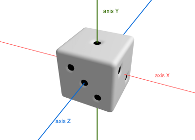
The rotation stored in the euler vector is the set of 3 rotations that are performed in YZX order with respect to the local coordinate system. So the first rotation goes around the local Y-axis (which is the same as the world Y-axis), then around local Z-axis (which may now be different from the world Z-axis), then local X rotation (which may be different from the world X-axis).
The first Y-rotation can be absolutely random and the dice will still be lying on the floor with side #1 looking up. It means we don’t need euler.y to compute the result.
Obviously, euler.z and euler.x have to be both a multiple of π/2 so we can go through possible combinations.
As mentioned, with euler.z = 0 and euler.x = 0 we get side #1.
With euler.z = 0, rotating the cube around it’s local X-axis to π/2, –π/2, and to –π (-π is equal to π here) leads with side #4, #3 and #6 orientation respectfully.
With euler.z = 0.5 the cube is rotated around the Z-axis to π/2, and we have side #2 on the top regardless of the X-rotation. In fact, the X-axis is now the same as the original Y so we got the Gimbal lock.
Same for the case of Z-rotation to –π/2. X-axis gets locked again and we always have side #5 on the top.
By the Euler angle definition, the second rotation (Z-rotation with YZX order) covers only the π range (while first and third rotations have 2 x π range). In other words, Z-rotation is only defined between –π/2 and π/2 so all the dice angle options are covered.
const eps = .1;
let isZero = (angle) => Math.abs(angle) < eps;
let isHalfPi = (angle) => Math.abs(angle - .5 * Math.PI) < eps;
let isMinusHalfPi = (angle) => Math.abs(.5 * Math.PI + angle) < eps;
let isPiOrMinusPi = (angle) => (Math.abs(Math.PI - angle) < eps || Math.abs(Math.PI + angle) < eps);

if (isZero(euler.z)) {
    if (isZero(euler.x)) {
        showRollResults(1);
    } else if (isHalfPi(euler.x)) {
        showRollResults(4);
    } else if (isMinusHalfPi(euler.x)) {
        showRollResults(3);
    } else if (isPiOrMinusPi(euler.x)) {
        showRollResults(6);
    } else {
        // landed on edge => wait to fall on side and fire the event again
        dice.body.allowSleep = true;
    }
} else if (isHalfPi(euler.z)) {
    showRollResults(2);
} else if (isMinusHalfPi(euler.z)) {
    showRollResults(5);
} else {
    // landed on edge => wait to fall on side and fire the event again
    dice.body.allowSleep = true;
}
Through this tutorial, we have explored the use of Three.js and cannon-es to create a dynamic and interactive dice roller. By manipulating 3D shapes, experimenting with different combinations of forces, and adjusting the properties of the physical bodies, we were able to create a realistic and engaging simulation. The user interface elements and additional code for this project can be found in the accompanying repository. We encourage you to download the project and experiment with different settings and parameters to further enhance your understanding and skills in animation and physics simulation. Have fun!
Check out the final demo and see the full code in the GitHub repo. 🎲 🤘


