
Free course recommendation: Master JavaScript animation with GSAP through 34 free video lessons, step-by-step projects, and hands-on demos. Enroll now →
CSS currently provides us with a way to apply color effects to images such as saturation, lightness, and contrast, among other effects, via the filter property and the filter functions that come with it.
We now have 11 filter functions in CSS that do a range of effects from blurring to changing color contrast and saturation, and more. We have a dedicated entry in the CSS Reference if you want to learn more about them.
This article is part of a series on SVG Filter effects. Check out the other articles in the series:
Albeit powerful and very convenient, CSS filters are also very limited. The effects we are able to create with them are often applicable to images and limited to color manipulation and basic blurring. So, in order to create more powerful effects that we can apply to a wider range of elements, we’ll need a wider range of functions. These functions are available today —and have been available for over a decade— in SVG. In this article, which is the first in a series about SVG filters, you will learn about the SVG filter functions — known as “primitives” — and how to use them.
CSS filters are imported from SVG. They are fairly more optimized versions of a subset of filter effects present in SVG, and that have been around in the SVG specification for years.
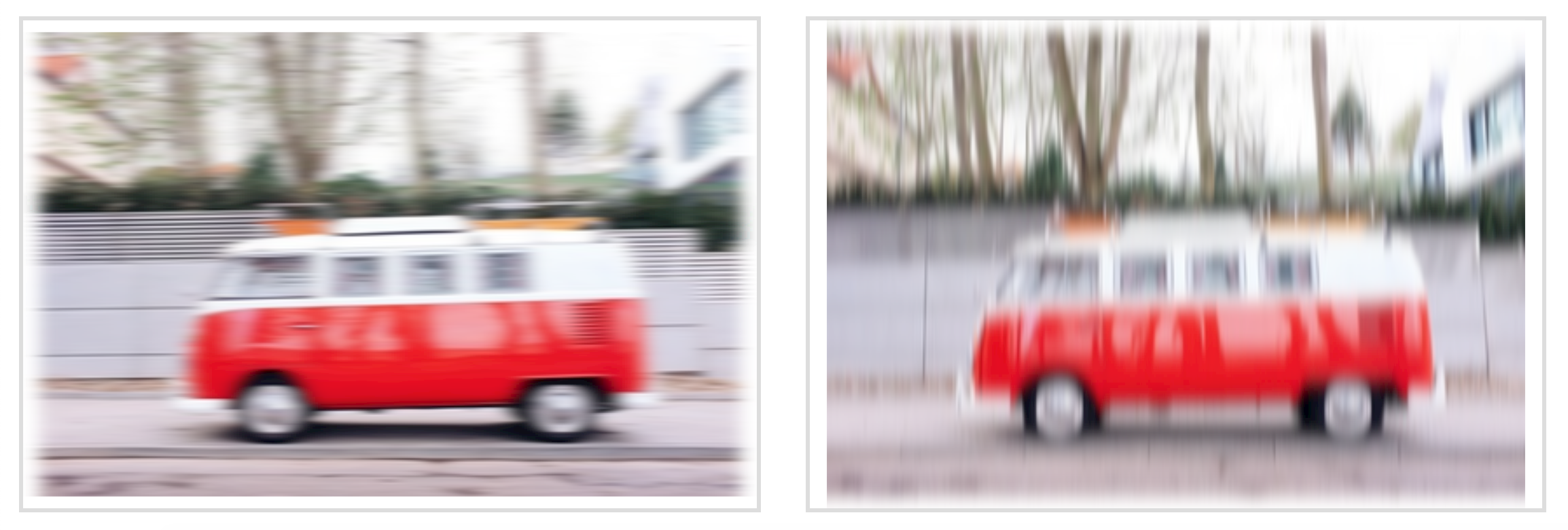
There are more filters effects in SVG than there are in CSS, and the SVG versions are more powerful and capable of far more complex effects than their CSS shortcuts. For example, it is currently possible to blur an element using the CSS blur() filter function. Applying a blur effect using this function will create a uniform Gaussian Blur to the element it is applied to. The following image shows the result of applying a 6px blur to an image in CSS:

The blur() function creates a blur effect that is uniformly applied in both directions — X & Y — on the image. But this function is merely a simplified and limited shortcut for the blur filter primitive available in SVG, which allows us to blur an image either uniformly, or apply a one-directional blur effect along either the X- or the Y-axis.
SVG filters can be applied to HTML elements as well as SVG elements. An SVG filter effect can be applied to an HTML element in CSS using the url() filter function. For example, if you have a filter effect with an ID “myAwesomeEffect” defined in your SVG (we’ll talk about defining filters effects in SVG shortly), you can apply that effect to an HTML element or image like this:
.el {
   filter: url(#myAwesomeEffect);
}
Best of all, as you’re going to see in this series, SVG filters are capable of creating Photoshop-grade effects in the browser, using a few lines of code. I hope this series will help demystify and unlock part of SVG Filters’ potential and inspire you to start using them in your own projects.
But what about browser support, you ask..?
Browser Support
Browser support for the majority of SVG filters is impressively good. How an effect is applied may, however, vary across a few browsers depending on the browser support for the individual filter primitives used in the SVG filter effect, as well as depending on any possible browser bugs. Browser support may also vary when the SVG filter is applied to SVG elements versus HTML elements.
I would recommend that you treat filter effects as an enhancement: you can almost always apply an effect as an enhancement on top of a perfectly usable filter-less experience. (Those of you who know me would know that I endorse a progressive enhancement approach to building UIs whenever possible.) So, we won’t be too concerned about browser support in this series.
Lastly, even though SVG Filter support is generally good, do keep in mind that some of the effects we will cover later in the series may be considered experimental. I will mention any major issues or bugs if and when there are any.
So, how do you define and create a filter effect in SVG?
The <filter> Element
Just like linear gradients, masks, patterns, and other graphical effects in SVG, filters have a conveniently-named dedicated element: the <filter> element.
A <filter> element is never rendered directly; its only usage is as something that can be referenced using the filter attribute in SVG, or the url() function in CSS. Such elements (elements that are not rendered unless explicitly referenced) are usually defined as templates inside <defs> elements in SVG. But an SVG <filter> doesn’t need to be wrapped in a defs element. Whether you wrap the filter in a defs element or not, it will simply not be displayed.
The reason for that is that a filter requires a source image to work on, and unless you explicitly define that source image by calling the filter on that source image, it won’t have anything to render, and so it doesn’t.
A very basic, minimal code sample defining an SVG filter and applying it to a source image in SVG would look like this:
<svg width="600" height="450" viewBox="0 0 600 450">
    <filter id="myFilter">
        <!-- filter effects go in here -->
    </filter>
    <image xlink:href="..."
           width="100%" height="100%" x="0" y="0"
           filter="url(#myFilter)"></image>
</svg>
The filter in the above code sample does nothing at this point because it is empty. In order to create a filter effect, you need to define a series of one or more filter operations that create that effect inside the filter. In other words, the filter element is a container to a series of filter operations that, combined, create a filter effect. These filter operations are called “Filter Primitives” in SVG.
Filter Primitives
So, in SVG, each <filter> element contains a set of filter primitives as its children. Each filter primitive performs a single fundamental graphical operation on one or more inputs, producing a graphical result.
A filter primitive is conveniently named after whatever graphical operation it performs. For example, the primitive that applies a Gaussian Blur effect to the source graphic is called feGaussianBlur. All primitives share the same prefix: fe, which is short for “filter effect”. (Again, names in SVG are conveniently chosen to resemble what an element is or does.)
The following snippet shows what a simple filter would look like if that filter were to apply a 5px Gaussian Blur to an image:
<svg width="600" height="450" viewBox="0 0 600 450">
    <filter id="myFilter">
        <feGaussianBlur stDeviation="5"></feGaussianBlur>
    </filter>
    <image xlink:href="..."
           width="100%" height="100%" x="0" y="0"
           filter="url(#myFilter)"></image>
</svg>
There are currently 17 filter primitives defined in the SVG Filter specification that are capable of extremely powerful graphical effects, including but not limited to noise and texture generation, lighting effects, color manipulation (on a channel by channel basis), and more.
A filter primitive works by taking a source graphic as input and outputting another one. And the output of one filter effect can be used as input to another. This is very important and very powerful because it means that you have an almost countless combination of filter effects and therefore you can create an almost countless number of graphical effects.
Each filter primitive can take one or two inputs and output only one result. The input of a filter primitive is defined in an attribute called in. The result of an operation is defined in the result attribute. If the filter effect takes a second input, the second input is set in the in2 attribute. The result of an operation can be used as input to any other operation, but if the input of an operation is not specified in the in attribute, the result of the previous operation is automatically used as input. If you don’t specify the result of a primitive, its result will automatically be used as input to the primitive that follows. (This will become clearer as we start looking into code examples.)
In addition to using the result(s) of other primitives as input, a filter primitive also accepts other types of inputs, the most important of which are:
- SourceGraphic: the element to which the entire filter is applied; for example, an image or a piece of text.
- SourceAlpha: this is the same as the
SourceGraphic, except that this graphic contains only the alpha channel of the element. For a JPEG image, for example, it is a black rectangle the size of the image itself.
You’ll find that you’ll sometimes want to use the source graphic as input and sometimes only its alpha channel. The examples we will cover in this post and the following posts will provide a clear understanding of when to use which.
This code snippet is an example of what a filter with a bunch of filter primitives as children could look like. Don’t worry about the primitives and what they do. At this point, just pay attention to how the inputs and outputs of certain primitives are being defined and used amongst them. I’ve added some comments to help.
<svg width="600" height="400" viewBox="0 0 850 650">
    <filter id="filter">
        <feOffset in="SourceAlpha" dx="20" dy="20"></feOffset>

        <!-- since the previous filter did not have a result defined and this following one
        does not have the input set, the result of the above primitive is automatically used
        as input to the following filter -->
        <feGaussianBlur stdDeviation="10" result="DROP"></feGaussianBlur>

        <!-- setting/defining the result names in all caps is a good way to make them more
        distinguishable and the overall code more readable -->
        <feFlood flood-color="#000" result="COLOR"></feFlood>

        <!-- This primitive is using the outputs of the previous two primitives as
        input, and outputting a new effect -->
        <feComposite in="DROP" in2="COLOR" operator="in" result="SHADOW1"></feComposite>

        <feComponentTransfer in="SHADOW1" result="SHADOW">
                <feFuncA type="table" tableValues="0 0.5"></feFuncA>
        </feComponentTransfer>

        <!-- You can use ANY two results as inputs to any primitive, regardless
        of their order in the DOM.-->
        <feMerge>
            <feMergeNode in="SHADOW"></feMergeNode>
            <feMergeNode in="SourceGraphic"></feMergeNode>
        </feMerge>
    </filter>
    <image xlink:href="..." x="0" y="0" width="100%" height="100%" filter="url(#filter)"></image>
</svg>
Now, the last concept I want to cover briefly before moving to our first filter example is the concept of a Filter Region.
The Filter Region
The set of filter operations need a region to operate on— an area they can be applied to. For example, you may have a complex SVG with many elements and you want to apply the filter effect only to a specific region or one or a group of elements inside that SVG.
In SVG, elements have “regions” whose boundaries are defined by the borders of the element’s Bounding Box. The Bounding Box (also abbreviated “bbox“) is the smallest fitting rectangle around an element. So for example for a piece of text, the smallest fitting rectangle looks like the pink rectangle in the following image.

Note that this rectangle might include some more white space vertically because the line height of the text is taken into consideration when calculating the height of the bounding box.
The default filter region of an element is the element’s bounding box. So if you were to apply a filter effect to our piece of text, the effect will be restricted to this rectangle, and any filter result that lies beyond the boundaries of it will be clipped off. Albeit sensible, this is not very practical because many filters will impact pixels slightly outside the boundaries of the bounding box and, by default, those pixels will end up being cut off.
For example, if we apply a blur effect to our piece of text, you can see the blur getting cut off at the left and right edges of the text’s bounding box:

So how do we prevent that from happening? The answer is: by extending the filter region. We can extend the region the filter is applied to by modifying the x, y, width and height attributes on the <filter> element.
According to the specification,
It is often necessary to provide padding space in the filter region because the filter effect might impact bits slightly outside the tight-fitting bounding box on a given object. For these purposes, it is possible to provide negative percentage values for ‘x’ and ‘y’, and percentage values greater than 100% for ‘width’ and ‘height’.
By default, filters have regions extending 10% the width and height of the bounding box in all four directions. In other words, the default values for the x, y, width and height attributes are as follows:
<filter x="-10%" y="-10%" width="120%" height="120%"
        filterUnits="objectBoundingBox">
    <!-- filter operations here -->
</filter>
If you omit these attributes on the <filter> element, these values will be used by default. You can also override them to extend or shrink the region as you need.
One thing to keep in mind is that the units used in the x, y, width and height attributes are dependent on which filterUnits value is in use. The filterUnits attribute defines the coordinate system for the x, y, width and height attributes. It takes one of two values:
objectBoundingBox: this is the default value. When thefilterUnitsisobjectBoundingBox, the values of thex,y,widthandheightattributes are percentages or fractions of the size of the element’s bounding box. This also means that you can use fractions as values instead of percentages if you prefer.userSpaceOnUse: whenfilterUnitsis set touserSpaceOnUsethe coordinates of thex,y,widthandheightattributes are set relative to the current user coordinate system in use. In other words, it is relative to the current coordinate system in use in the SVG, which uses pixels as a unit and is, usually, relative to the size of the SVG itself, assuming theviewBoxvalues matches that of the initial coordinate system. (You can learn all you need to know about coordinate systems in SVG in this post I wrote a few years ago.)
<!-- Using objectBoundingBox units -->
<filter id="filter"
        x="5%" y="5%" width="100%" height="100%">

<!-- Using userSpaceOnUse units -->
<filter id="filter"
        filterUnits="userSpaceOnUse"
        x="5px" y="5px" width="500px" height="350px">
Quick Tip: Visualizing the current filter region with feFlood
If you ever need to see the extent of your filter region you can visualize it by flooding the filter region with color. Conveniently, a filter primitive called feFlood exists whose sole purpose is to do exactly that: fill the current filter region with a color that you specify in the flood-color attribute.
So, assuming we have a piece of text whose filter region we want to visualize, the code would look as simple as:
<svg width="600px" height="400px" viewBox="0 0 600 400">
    <filter id="flooder" x="0" y="0" width="100%" height="100%">
        <feFlood flood-color="#EB0066" flood-opacity=".9"></feFlood>
    </filter>

    <text dx="100" dy="200" font-size="150" font-weight="bold" filter="url(#flooder)">Effect!</text>
</svg>
As you can see in the above code snippet, the feFlood primitive also accepts a flood-opacity attribute which you can use to make the flood color layer translucent.
The above snippet floods the filter region with a pink color. But here is the thing: when you flood the region with color, you’re literally flooding it with color, meaning that the color will cover everything in the filter region, including any elements and effects you’ve created before, as well as the text itself. After all, this is what the definition of flooding is, right?

In order to change that, we need to move the color layer to the “back” and show the source text layer on top.
Whenever you have multiple layers of content that you want to display on top of each other in an SVG filter, you can use the <feMerge> filter primitive. As its name suggests, the feMerge primitive is used to merge together layers of elements or effects.
The <feMerge> primitive does not have an in attribute. To merge layers, two or more <feMergeNode>s are used inside feMerge, each of which has its own in attribute that represents a layer that we want to add.
Layer (or “node”) stacking depends on the <feMergeNode> source order — the first <feMergeNode> will be rendered “behind” or “below” the second. The last <feMergeNode> represents the topmost layer. And so on.
So, in our text example, the flood color is a layer, and the source text (the source graphic) is another layer, and we want to place the text on top of the flood color. Our code will hence look like this:
<svg width="600px" height="400px" viewBox="0 0 600 400">
	<filter id="flooder">
		<feFlood flood-color="#EB0066" flood-opacity=".9" result="FLOOD"></feFlood>

		<feMerge>
				<feMergeNode in="FLOOD" />
				<feMergeNode in="SourceGraphic" />
			</feMerge>
	</filter>

	<text dx="100" dy="200" font-size="150" font-weight="bold" filter="url(#flooder)">Effect!</text>
</svg>
Notice how I named the result of the feFlood in the result attribute so that I can reference that name in the <feMergeNode> as input. Since we want to display the source text on top of the flood color, we reference this text using SourceGraphic. The following is a live demo of the result:
See the Pen Filter Region Visualization with feFlood by Sara Soueidan (@SaraSoueidan) on CodePen.
Now that we’ve gotten a quick introduction into the world of SVG filters with this demo, let’s create a simple SVG drop shadow.
Applying a drop shadow to an image
Let me start with a quick disclaimer: you’re better off creating a simple drop shadow using the CSS drop-shadow() filter function. The SVG filter way is much more verbose. After all, as we mentioned earlier, the CSS filter functions are convenient shortcuts. But I want to cover this example anyway as a simple entry point to the more complex filter effects we’ll cover in the coming articles.
So, how is a drop shadow made?
A drop shadow is usually a light-gray layer behind—or underneath—an element, that has the same form (or shape) as the element itself. In other words, you can think of it as a blurred gray copy of the element.
When creating SVG filters, we need to think in steps. What steps are needed to achieve a particular effect? For a drop shadow, a blurred gray copy of the element can be created by blurring a black copy of the element and then colorizing that black copy (making it gray). Then that newly created blurred grey copy is positioned behind the source element, and offset a little in both directions.
So we’re going to start by getting a black copy of our element and blurring it. The black copy can be created by using the alpha channel of the element, using SourceAlpha as input to our filter.
The feGaussianBlur primitive will be used to apply a Gaussian blur to that SourceAlpha layer. The amount of blur you need is specified in the stdDeviation (short for: Standard Deviation) attribute. If you provide one value to the stdDeviation attribute, that value will be used to apply a uniform blur to the input. You can also provide two numerical values— the first will be used to blur the element in the horizontal direction and the second will be used to apply a vertical blur. For a drop shadow, we need to apply a uniform blur, so our code will start with this:
<svg width="600" height="400" viewBox="0 0 850 650">
    <filter id="drop-shadow">

        <-- Grab a blakc copy of the source image and blur it by 10 -->
        <feGaussianBlur in="SourceAlpha" stdDeviation="10" result="DROP"></feGaussianBlur>

    </filter>
    <image xlink:href="..." x="0" y="0" width="100%" height="100%" filter="url(#drop-shadow)"></image>
</svg>
The above code snippet results in the following effect, where only the blurred alpha channel of the image is rendered at this point:

Next, we want to change the color of the drop shadow and make it grey. We will do that by applying a flood color to the filter region and then compositing that flood color layer with the drop shadow layer we have created.
Compositing is the combining of a graphic element with its backdrop. A backdrop is the content behind the element and is what the element is composited with. In our filter, the Flood color is the upper layer, and the blurred shadow is its backdrop (because it lies behind it). We will see the feComposite primitive more in the upcoming articles, so if you’re not familiar with what compositing is and how it works, I have a very comprehensive introductory article on my blog that I recommend checking out.
The feComposite primitive has an operator attribute which is used to specify which composite operation we want to use.
By using the in composite operator, the flood color layer will be “cropped” and only the area of the color that overlaps with our shadow layer will be rendered, and the two layers will be blended where they intersect, which means that the grey color will be used to colorize our black drop shadow.
The feComposite primitive requires two inputs to operate on, specified in the in and in2 attributes. The first input is our color layer, and the second input is our blurred shadow backdrop. With the composite operation specified in the operator attribute, our code now looks like this:
<svg width="600" height="400" viewBox="0 0 850 650">
    <filter id="drop-shadow">
        <feGaussianBlur in="SourceAlpha" stdDeviation="10" result="DROP"></feGaussianBlur>

        <feFlood flood-color="#bbb" result="COLOR"></feFlood>

        <feComposite in="COLOR" in2="DROP" operator="in" result="SHADOW"></feComposite>


    </filter>
    <image xlink:href="..." x="0" y="0" width="100%" height="100%" filter="url(#drop-shadow)"></image>
</svg>
Notice how the results of the feGaussianBlur and the feFlood primitives are used as inputs for feComposite. Our demo now looks like this:

Before we layer our original image on top of the drop shadow, we want to offset the latter vertically and/or horizontally. How much you offset the shadow and in which direction is completely up to you. For this demo, I’ll assume we have a source light coming from the top left corner of our screen, so I will move it by a few pixels down to the right.
To offset a layer in SVG, we use the feOffset primitive. In addition to the in and result attributes, this primitive takes two main attributes: dx and dy, which determine the distance by which you want to offset the layer along the x and y axes, respectively.
After offsetting the drop shadow, we will merge it with the source image using feMerge, similar to how we merged the text and flood color in the previous section— one mergeNode will take our drop shadow as input, and another mergeNode will layer the source image using SourceGraphic as input. Our final code now looks like this:
<svg width="600" height="400" viewBox="0 0 850 650">
    <filter id="drop-shadow">

        <!-- Get the source alpha and blur it; we'll name the result "DROP"  -->
        <feGaussianBlur in="SourceAlpha" stdDeviation="10" result="DROP"></feGaussianBlur>

        <!-- flood the region with a ligh grey color; we'll name this layer "COLOR" -->
        <feFlood flood-color="#bbb" result="COLOR"></feFlood>

        <!-- Composite the DROP and COLOR layers together to colorize the shadow. The result is named "SHADOW"  -->
        <feComposite in="COLOR" in2="DROP" operator="in" result="SHADOW"></feComposite>

        <!-- Move the SHADOW layer 20 pixels down and to the right. The new layer is now called "DROPSHADOW"  -->
        <feOffset in="SHADOW" dx="20" dy="20" result="DROPSHADOW"></feOffset>

        <!-- Layer the DROPSHADOW and the Source Image, ensuring the image is positioned on top (remember: MergeNode order matters)  -->
        <feMerge>
            <feMergeNode in="DROPSHADOW"></feMergeNode>
            <feMergeNode in="SourceGraphic"></feMergeNode>
        </feMerge>
    </filter>

    <!-- Apply the filter to the source image in the `filter` attribute -->
    <image xlink:href="..." x="0" y="0" width="100%" height="100%" filter="url(#drop-shadow)"></image>
</svg>
And the following is a live demo of the above code:
See the Pen Drop Shadow: Tinted shadow with feComposite by Sara Soueidan (@SaraSoueidan) on CodePen.
And that is how you apply a filter effect in SVG using SVG filters. You’ll find that this effect works across all major browsers.
There is another way…
There is another, more common way of creating a drop shadow. Instead of creating a black shadow and applying color to it to make it lighter, you could apply transparency to it, thus making it translucent and, consequently, lighter.
In the previous demo, we learned how to apply color to the drop shadow using feFlood, which is a coloring technique you’ll probably find yourself needing and using often. This is why I thought it was necessary to cover. It is also useful to learn because this is the way to go if you want to create a shadow that, for whatever reason, has a colorful shadow, for example, instead of a black or grey one.
In order to change the opacity of a layer, you can use either the feColorMatrix primitive or the feComponentTransfer primitive. I’ll talk about the feComponentTransfer primitive in more detail in upcoming articles, so I’ll use feColorMatrix to reduce the opacity for our shadow now.
The feColorMatrix primitive deserves an article of its own. For now, I highly recommend reading Una Kravet’s article which is a great introduction with really good examples.
In short, this filter applies a matrix transformation to the R(Red), G(Green), B(Blue), and A(Alpha) channels of every pixel in the input graphic to produce a result with a new set of color and alpha values. In other words, you use a matrix operation to manipulate the colors of your object. A basic color matrix looks like this:
<filter id="myFilter">
    <feColorMatrix
      type="matrix"
      values="R 0 0 0 0
              0 G 0 0 0
              0 0 B 0 0
              0 0 0 A 0 "/>
    </feColorMatrix>
</filter>
Once again I recommend checking Una’s article out to learn more about this syntax.
Since we only want to reduce the opacity of our shadow, we will use an identity matrix that does not alter the RGB channels, but we will reduce the value of the alpha channel in that matrix:
<filter id="filter">

        <!-- Get the source alpha and blur it,  -->
        <feGaussianBlur in="SourceAlpha" stdDeviation="10" result="DROP"></feGaussianBlur>

        <!-- offset the drop shadow  -->
        <feOffset in="SHADOW" dx="20" dy="20" result="DROPSHADOW"></feOffset>

        <!-- make the shadow translucent by reducing the alpha channel value to 0.3  -->
        <feColorMatrix type="matrix" in="DROPSHADOW" result="FINALSHADOW"
                                  values="1 0 0 0 0
					  0 1 0 0 0
					  0 0 1 0 0
					  0 0 0 0.3 0">
        </feColorMatrix>

        <!-- Merge the shadow and the source image  -->
        <feMerge>
            <feMergeNode in="FINALHADOW"></feMergeNode>
            <feMergeNode in="SourceGraphic"></feMergeNode>
        </feMerge>
    </filter>
And this is our live demo:
See the Pen Drop Shadow: Translucent shadow with feColorMatrix by Sara Soueidan (@SaraSoueidan) on CodePen.
Final Words
In this series, I will try to steer away from the very technical definitions of filter operations and stick to simplified and friendly definitions. Often, you don’t need to get into the gnarly little details of what happens under the hood, so getting into those details would only add to the complexity of the articles, possibly make them less digestible, and would bring little benefit. Understanding what a filter does and how to use it is more than enough, in my opinion, to take advantage of what it has to offer. If you do want to get into more details, I recommend consulting the specification to start. That said, the spec may prove to be of little help, so you’ll probably end up doing your own research on the side. I’ll provide a list of excellent resources for further learning in the final article of this series.
Now that we’ve covered the basics of SVG filters and how to create and apply one, we will look into more examples of effects using more filter primitives in the upcoming articles. Stay tuned.


Shukran Sara!
There is a typo in your code for ‘filter with a bunch of filter primitives as children’
There is this line of code:
which has a typographic quote character ‘“’ at the result attribute, but it has to be a normal double quote ‘”‘.
Thanks for catching that! Fixed 🙂
In the same code there are two more typos:
has to be
———–^
and
sjould be
————————————–^
Not sure what you mean here, could you be more specific? Thanks, ML
I think you typed code that wasn’t rendered so not sure what you meant. I can’t spot any error in the code at the moment. What are my eyes missing?
In the Filter Primitives section, first code snippet, feGaussianBlur element’s attribute stDeviation=”5″ typo, should be stdDeviation=”5″
Very well written article that is easy to follow and makes me want to explore SVG filter effects more in depth. Thanks for writing!
Sarah Soueidan, Mary Lou are my heroins forever. Thank you for sharing your amazing insights and knowledge with us.
Thanks for a great article, Sara.
Quick question: Is there a way to increase the area of an SVG animation, similarly to how you increased the filter area? When I animate groups within svg’s, and let’s say translate them from the side or scale from a higher number down to 1, the element is cut off by the SVG viewport.
Thanks again.
Hey Magnus!
If I understand the problem correctly, I believe expanding the SVG canvas (internally) should do the trick. In other words, the viewport would remain unchanged but the overall area inside the SVG increases. You can do that by expanding the viewBox (increasing the width and height values while decreasing the x and y values).
If you’re unfamiliar with the viewBox and how it works, I recommend checking out the SVG Coordinate Systems and Transformations series on my blog. The first article covers the viewport and viewBox in depth.
I hope this helps. Thanks for reading!
Thank you for this excellent introductory article which provides a lot of food for thought.