
Free course recommendation: Master JavaScript animation with GSAP through 34 free video lessons, step-by-step projects, and hands-on demos. Enroll now →
If you’ve been following the WebGL/Three.js community, chances are you’ve come across the great work of @Mister_Prada. We’re thrilled to have him share his expertise on Codrops, where he walks us through the process of building a mesmerizing procedural vortex!
Inspired by the work of cmzw, I started by making a simple fragment shader and wanted to take it further by turning it into a volumetric effect inside a glass sphere using TSL (Three.js Shader Language). As I worked on this, I realized how much composition and balance matter, especially in 3D. At EgorovAgency, I am always learning, and collaborating with 3D artists has helped me understand how to create visuals that feel right.
This tutorial walks through the whole process from the basic 2D shader to a swirling vortex inside a glass sphere. Let’s start by setting up the base geometry.
Step 1: Creating a Plane for 2D Display
To begin, we need a basic 2D plane that will serve as the foundation for our procedural vortex. This step involves creating a plane geometry with a high vertex count (512×512) to ensure smooth deformations later. We then rotate it to lie flat along the XZ plane and apply a basic material with a wireframe mode for visualization. Finally, the plane is added to the scene, setting the stage for further transformations.
const planeGeometry = this.planeGeometry = new THREE.PlaneGeometry(
    this.uniforms.uResolution.value.x,
    this.uniforms.uResolution.value.y,
    512,
    512
)

planeGeometry.rotateX( -Math.PI * 0.5 )
const material = new THREE.MeshBasicNodeMaterial( {
    wireframe: true,
    transparent: true,
} )

this.planeMesh = new THREE.Mesh( planeGeometry, material )

this.scene.add( this.planeMesh )
Step 2: Creating a Fragment Shader for the Plane
First, we need to add all the necessary imports to work with TSL.
import {
    sin, positionLocal, time, vec2, vec3, vec4, uv, uniform, color, fog, rangeFogFactor,
    texture, If, min, range, instanceIndex, timerDelta, step, timerGlobal,
    mix, max, uint, cond, varying, varyingProperty, Fn, struct, output, emissive, diffuseColor, PI, PI2,
    oneMinus, cos, atan, float, pass, mrt, assign, normalize, mul, log2, length, pow, smoothstep,
    screenUV, distance, instancedArray, instancedBufferAttribute, attribute, attributeArray, pointUV,
    select, equals
} from 'three/tsl'
Next, we need to create a function for colorNode to start outputting color to the plane using TSL.
material.colorNode = Fn( () => {
   return vec4( 1, 0, 0, 1)
} )()
vec4( 1, 0, 0, 1) → Red, Green, Blue, Alpha.Now, we need to display the UV coordinates.
material.colorNode = Fn( () => {
   const _uv = uv();

   return vec4(uv.xy, 0, 1);
} )()
Next, we need to move the UV coordinate center to the middle of the plane, making it easier to manipulate in the fragment shader. For a square plane, multiplying by 2 and subtracting 1 is sufficient. However, if you’re working with a rectangular plane—such as a typical screen—you also need to multiply uv.y by the aspect ratio.
material.colorNode = Fn( () => {
   const uResolution = this.uniforms.uResolution;
   const aspect = uResolution.x.div( uResolution.y );
   const _uv = uv().mul( 2 ).sub( 1 );
   _uv.y.mulAssign( aspect );

   return vec4(_uv.xy, 0, 1);
} )()
Now, we need to create a vec3() that includes the UV coordinates and a third component, which we will use for infinite vector movement. This allows our vortex to move inward along the UV coordinates, a technique commonly seen in Blender Nodes.
...
const color = vec3( _uv, 0.0 ).toVar();
color.z.addAssign( 0.5 );
color.assign( normalize( color ) );
color.subAssign( mul( this.uniforms.speed, vec3( 0.0, 0.0, time ) ) );

return vec4(color, 1.0);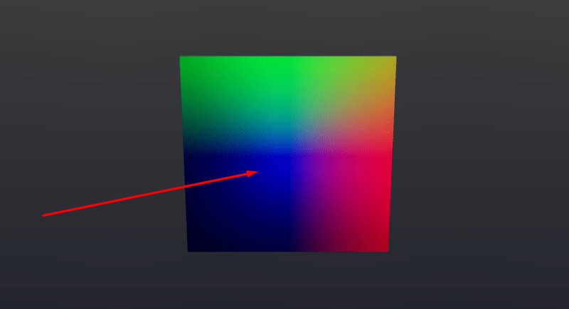
...
const angle = float( log2( length( _uv ) ).negate() ).toVar();
color.assign( rotateZ( color, angle ) );

return vec4(color, 1.0);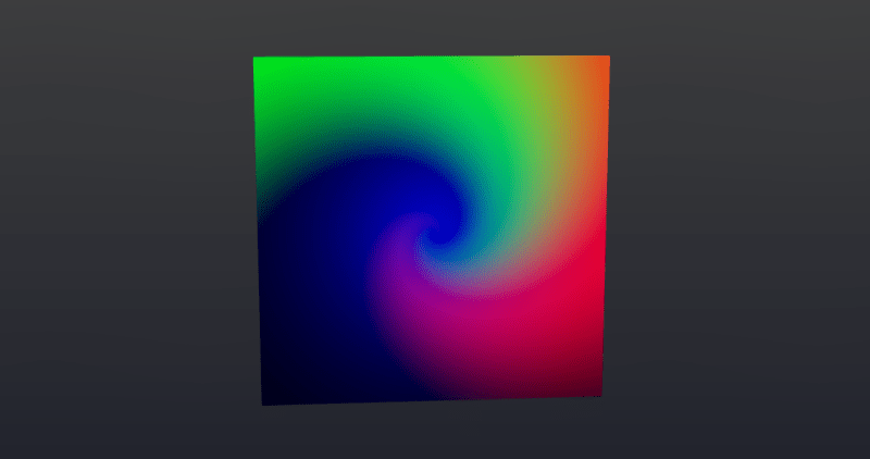
angle variable.Next, we need to add Fractal Brownian Motion (FBM) noise to the noiseColor variable.
...
const frequency = this.uniforms.frequency;
const distortion = this.uniforms.distortion;

color.x.assign( fbm3d( color.mul( frequency ).add( 0.0 ), 5 ).add( distortion ) );
color.y.assign( fbm3d( color.mul( frequency ).add( 1.0 ), 5 ).add( distortion ) );
color.z.assign( fbm3d( color.mul( frequency ).add( 2.0 ), 5 ).add( distortion ) );
const noiseColor = color.toVar();

return vec4(color, 1.0);Now, let’s isolate the center and enhance it with an emission effect.
...
noiseColor.mulAssign( 2 );
noiseColor.subAssign( 0.1 );
noiseColor.mulAssign( 0.188 );
noiseColor.addAssign( vec3(_uv.xy, 0 ) );

const noiseColorLength = length( noiseColor );
noiseColorLength.assign( float( 0.770 ).sub( noiseColorLength ) );
noiseColorLength.mulAssign( 4.2 );
noiseColorLength.assign( pow( noiseColorLength, 1.0 ) );

return vec4( vec3(noiseColorLength), 1 );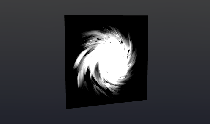
noiseColorLength float component.Now, let’s highlight the outer edges.
...
   const fac = length( _uv ).sub( facture( color.add( 0.32 ) ) );
   fac.addAssign( 0.1 );
   fac.mulAssign( 3.0 );

   return vec4( vec3(fac), 1);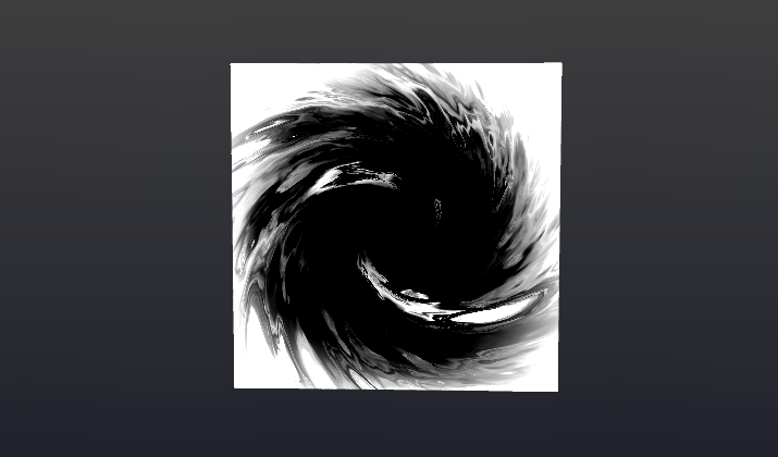
_uv by a specific value, the entire image can be shrunk toward the center, with the transparent part removing any excess.Now, let’s create a glow effect in the center.
const emissionColor = emission( this.uniforms.emissionColor, noiseColorLength.mul( this.uniforms.emissionMultiplier ) );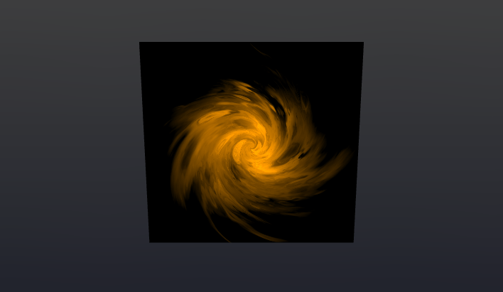
Next, we blend everything into a single color.
...
color.assign( mix( emissionColor, vec3( fac ), fac.add( 1.2 ) ) );
return vec4( color, 1 );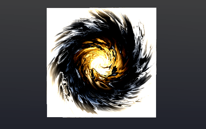
Finally, we add an alpha value to remove unnecessary parts.
const alpha = float( 1 ).sub( fac );

return vec4( color, alpha );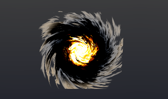
Step 3: Changing the Geometry Position Based on the Texture
We separate the texture code into a dedicated function that accepts uv as an input parameter. It’s also important to define a varying variable, since we will call the texture code inside the vertex shader. By passing this variable to the fragment shader, we avoid redundant texture rendering and can access its color directly.
// Varyings
varyings = {
    vSwirl: varying( vec4( 0 ), 'vSwirl' )
}

this.swirlTexture = Fn( ( params ) => {
   const _uv = params.uv.mul( 1 );
   ...

   // Assign to varying
   this.varyings.vSwirl.assign( color );

   return vec4( noiseColor, alpha );
} )
Since we are using FBM noise, which includes a Z component, we can mix our texture with the geometry’s position. We add the texture data to positionLocal, while the remaining adjustments are for refining the appearance. Make sure to orient the geometry horizontally so that the Y-axis behaves correctly inside the shader.
...
planeGeometry.rotateX( -Math.PI * 0.5 ); // Align to floor surface

material.positionNode = Fn( () => {
   const uResolution = this.uniforms.uResolution;
   const aspect = uResolution.x.div( uResolution.y );
   const _uv = uv().mul( 2 ).sub( 1 );
   _uv.y.mulAssign( aspect );
   _uv.mulAssign( 1.1 );

   const swirl = this.swirlTexture( { uv: _uv } );

   const finalPosition = positionLocal;

   finalPosition.y.addAssign( swirl.g.mul( 0.9 ) );

   return finalPosition;
} )();Step 4: Converting the Plane to Particles
Now, we can remove the plane from the scene and replace it with particles. We create two buffers for position and UV coordinates, extracted from planeGeometry. Then, we define a new function for positionNode, which will utilize the texture we created earlier and pass the uvA coordinates into it.
const positionAttribute = new THREE.InstancedBufferAttribute( new Float32Array( this.planeGeometry.attributes.position.array ), 3 );
const pos = instancedBufferAttribute( positionAttribute );

const uvAttribute = new THREE.InstancedBufferAttribute( new Float32Array( this.planeGeometry.attributes.uv.array ), 2 );
const uvA = instancedBufferAttribute( uvAttribute );

const particleMaterial = new THREE.SpriteNodeMaterial( {} );

particleMaterial.positionNode = Fn( () => {

   const uResolution = this.uniforms.uResolution;
   const aspect = uResolution.x.div( uResolution.y );

   const _uv = uvA.mul( 2 ).sub( 1 );
   _uv.y.mulAssign( aspect );

   const swirl = this.swirlTexture( { uv: _uv } );

   const finalPosition = pos.toVar();

   finalPosition.y.addAssign( swirl.g );

   return finalPosition;
} )();

particleMaterial.scaleNode = this.uniforms.size;

const particlesMesh = this.particlesMesh = new THREE.Mesh( new THREE.PlaneGeometry( 1, 1 ), particleMaterial );
particlesMesh.count = this.planeGeometry.attributes.position.count;
particlesMesh.frustumCulled = false;
Let’s add a condition that removes unnecessary particles from the camera’s view based on the alpha channel of the texture.
particleMaterial.positionNode = Fn( () => {

...

   If( swirl.a.lessThan( this.uniforms.radius ), () => {
       finalPosition.xyz.assign( vec3( 99999999 ) );
   } );

   return finalPosition;
} )();
Now, let’s add color to our vortex. We will store the color separately in a texture, as it differs slightly from the one used for the particle vertices.
this.swirlTexture = Fn( ( params ) => {

   ...

   // Assign color to varying
   this.varyings.vSwirl.assign( color );

   ...

} );

particleMaterial.colorNode = Fn( () => {
   return this.varyings.vSwirl;
} )();Step 4: Creating the Glass Sphere
We start by creating a standard sphere and applying MeshPhysicalNodeMaterial to it. This material allows us to create a realistic glass effect in Three.js. The necessary parameters have already been predefined and added to the uniforms.
uniforms = {
  color: uniform( new THREE.Color( 0xffffff ) ),
  metalness: uniform( 0.0 ),
  roughness: uniform( 0 ),
  ior: uniform( 1.5 ),
  thickness: uniform( 0.3 ),
  clearcoat: uniform( 0.73 ),
  dispersion: uniform( 5.0 ),
  attenuationColor: uniform( new THREE.Color( 0xffffff ) ),
  attenuationDistance: uniform( 1 ),
  //alphaMap: texture,
  //envMap: hdrEquirect,
  envMapIntensity: uniform( 1 ),
  transmission: uniform( 1 ),
  specularIntensity: uniform( 1 ),
  specularColor: uniform( new THREE.Color( 0xffffff ) ),
  opacity: uniform( 1 ),
  side: THREE.DoubleSide,
  transparent: true
};

const sphereGeometry = new THREE.SphereGeometry( 2.3, 32, 32 );
const sphereMaterial = this.sphereMaterial = new THREE.MeshPhysicalNodeMaterial( {
   color: this.uniforms.color.value,
   metalness: this.uniforms.metalness.value,
   roughness: this.uniforms.roughness.value,
   ior: this.uniforms.ior.value,
   dispersion: this.uniforms.dispersion.value,
   thickness: this.uniforms.thickness.value,
   clearcoat: this.uniforms.clearcoat.value,
   //alphaMap: texture,
   //envMap: hdrEquirect,
   envMapIntensity: this.uniforms.envMapIntensity.value,
   transmission: this.uniforms.transmission.value,
   specularIntensity: this.uniforms.specularIntensity.value,
   specularColor: this.uniforms.specularColor.value,
   opacity: this.uniforms.opacity.value,
   side: THREE.DoubleSide,
   transparent: false,
});

const sphereMesh = new THREE.Mesh( sphereGeometry, sphereMaterial );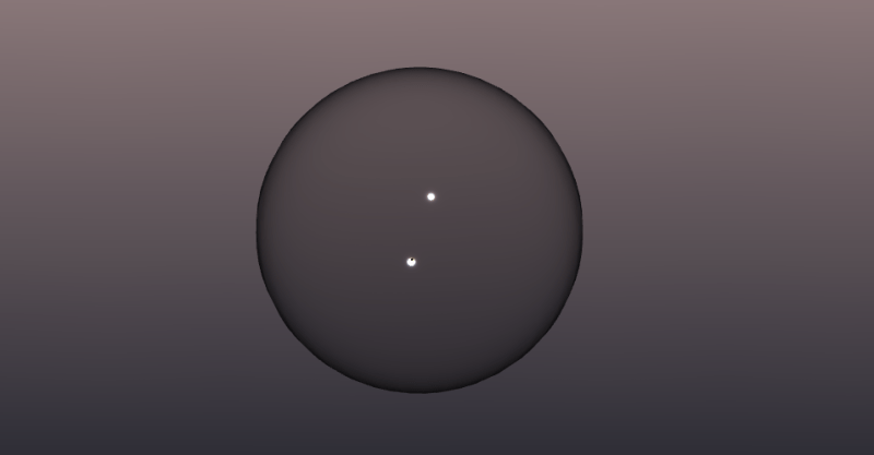
You may have noticed that the sphere still looks somewhat incomplete. To enhance its appearance, we will add an EnvironmentMap—preferably one featuring stars ⭐—to give it a more immersive and realistic look.
const hdriTexture = this.resources.items.hdriTexture;

hdriTexture.mapping = THREE.EquirectangularReflectionMapping;

this.scene.environment = hdriTexture;Step 5: Final Adjustments
Now, let’s add the vortex inside our scene and fine-tune the parameters to achieve the desired effect.
Recommendations for Optimization
- Reduce the number of particles and their size to minimize overlaps.
- Use Storage (WebGPU only) for improved performance.
- Replace the FBM function with a precomputed noise texture.
- Consider using a lower-polygon shape, like a cube, instead of the glass sphere, and apply normals to create interesting interior distortions.
- Pre-render the vortex texture and simply rotate the geometry inside, which can significantly boost performance.
If you’re feeling experimental, you could try creating a sphere with cutouts, adding god rays inside, and surrounding it with fog. I haven’t tried this myself, but it sounds like it could look really cool! 🙂


